Pressure Vessel Construction: Lower Pressure Makes it Easier
In the early 1950s, PWR pressure vessels large enough for a submarine plant were within the capabilities of the existing manufacturing infrastructure, but vessels large enough for electrical power generating stations were not.
Like the American pressurized water reactor systems, gas cooled reactors operate at elevated pressures. Unlike water, however, which is kept under extreme pressure in a reactor to prevent it from changing phase, carbon dioxide is kept under pressure in a reactor to improve its ability to remove heat by increasing its density.
The actual pressure used is also different. While PWRs often operate with their coolant at a pressure of 150 bar or more, the early CO2 reactors used a coolant system pressure of only 8 bar. This lower pressure implies a much different type of pressure vessel construction.
Rolled Steel vs Steel Plates
Pressurized water reactors, because of their extremely high pressures and the safety implications of a failure to maintain that pressure, use a core container that is very difficult and expensive to build.
In general, the containers are shaped in the form of cylinders with semi-spherical ends. The cylinder walls are made of single sheets of thick, high-strength steel that are painstakingly rolled into cylinders and welded. The plate steel may be as thick as 22 to 25 cm. The inside of the cylinder is normally lined with stainless steel for corrosion resistance.
The manufacture of these pressure vessels must take place under controlled shop conditions and requires specialized, expensive equipment. You can imagine what kind of machinery is needed to form 3.6 meter diameter, 3.8 meter high cylinders (these are typical large PWR dimensions) out of slabs of 22 cm thick steel. If you have any experience with welding, you can imagine how difficult, time consuming and expensive it is to weld that material in such a way that the weld is at least as strong as the plate steel.
The pressure vessel for the early pressurized water reactors was one of the “critical path” items. That means that it played a large role in determining the schedule needed for plant completion. In the beginning of Rickover’s quest for a submarine reactor plant, the capabilities of pressure vessel manufacturers were limited. In the early 1950s, PWR pressure vessels large enough for a submarine plant were within the capabilities of the existing manufacturing infrastructure, but vessels large enough for electrical power generating stations were not.
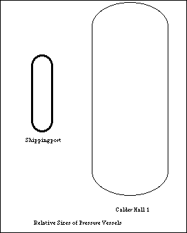
Fortunately for the gas cooled reactor designers, they only needed pressure vessels able to operate under pressures of 8 bar instead of 150 bar. Instead of needing a shop manufactured vessel with 22 cm thick walls, the reactor at Calder Hall only needed walls that were slightly more than 5 cm thick.
Of course, a reactor using natural uranium and gas cooling will be significantly larger than a similar capacity pressurized water reactor. The Calder Hall reactor, with a capacity of 30 MWe was almost 22 meters long and over 11 meters in diameter.
Fortunately for the British reactor designers, with a required thickness of only 5 cm, fabrication techniques were readily available to construct vessels of almost unlimited size by welding steel plates together at the job site. This technology was well established and used in other large scale industrial enterprises like oil refineries and conventional power plants.
There were also fewer reactor safety implications associated with gas cooled reactor pressure vessels. Any loss of pressure caused by a leak would be slow because a large portion of a large volume of pressurized gas would have to leak out. Even if the system pressure dropped all the way to atmospheric pressure (1 bar) the circulators would be able to move plenty of gas to remove the reactor heat generated after shutdown.
In contrast, a PWR can lose pressure very rapidly if enough fluid leaks out to allow steam voids to form. Steam formation in a PWR can stop coolant flow, since pumps designed to move water do a poor job of moving steam.
The task of building adequate pressure vessels for gas cooled reactors used proven technology and had a shorter time line that the equivalent task for pressurized water reactors. Instead of designing, building and testing large scale factory equipment and developing stringent test procedures, all the British and French had to do to begin building their reactors was to assemble a team of skilled welders and purchase materials from existing suppliers.
The site fabricated vessels could be built even in places without the infrastructure to support the transportation of 200 to 400 ton manufactured steel vessels. This was a significant advantage for power facilities located in remote areas without adequate road or rail beds for the needed equipment.
Reinforced Concrete
The lower pressures associated with gas cooled reactors allowed the French to proceed in an entirely different direction for their pressure vessels. Instead of depending on thick steel with welding to join the pieces, the French designed vessels based on prestressed concrete lined with a thin steel layer for leak tightness.
This type of vessel can be built to be almost any size; they are similar in nature to the enormous containment buildings that surround the entire primary system of pressurized water reactors. Their cost is somewhat lower than welded steel because of lower material and labor costs. They also serve the useful function of shielding people from the high temperatures and radiation associated with nuclear reactor operation.


